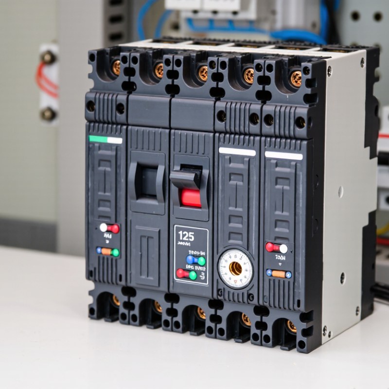
125 Amp MCCB Best Choice for Global Buyers?
Global electrical systems are becoming more demanding, yet buyers still need practical protection rather than impressive specifications. The International Energy Agency’s Electricity 2024 report projects global electricity demand to grow by an average of 3.2% annually from 2024 to 2026. That growth increases pressure on commercial buildings, factories, data centers, and renewable-energy installations. In these applications, a 125amp Mccb can provide a useful balance between feeder protection, installation space, and operating capacity.
But “best choice” is never determined by amperage alone. A 125 A molded case circuit breaker must match the system voltage, pole configuration, interrupting capacity, trip characteristics, and available fault current. IEC 60947-2 defines important requirements for low-voltage circuit breakers, while UL 489 is widely referenced in North American installations. Buyers should also compare Icu, Ics, short-circuit current ratings, temperature derating, and accessory compatibility. Small details matter. A cramped panel can turn routine maintenance into a costly interruption.
Market research often reports steady growth in circuit-breaker demand, driven by grid upgrades, industrial automation, and renewable integration. However, market forecasts do not replace engineering verification. A product may perform well in one region but fail a local certification or coordination review. That assumption deserves testing. Experienced purchasers should request test certificates, factory quality records, datasheets, and traceable production information. The right 125amp Mccb is therefore not simply the cheapest or most powerful option. It is the model that fits the complete electrical design, installation environment, and compliance requirements. Mistakes remain possible, especially when product labels hide important rating differences.
What Is a 125 Amp MCCB and How Does It Work?
A 125 amp MCCB is a molded case circuit breaker designed to carry up to 125 amperes under specified conditions. It protects cables, motors, and distribution panels from overloads and short circuits. The 125 amp rating is not a universal promise. Ambient temperature, enclosure size, installation method, and conductor selection can affect safe operation.
Inside the breaker, a thermal element responds to prolonged overcurrent. A bimetal strip heats, bends, and releases the trip mechanism. This action usually takes time, allowing brief starting currents to pass. During a short circuit, the magnetic element reacts almost instantly. It separates the contacts and sends the fault current into an arc-extinguishing chamber. The handle may move to a tripped position. After inspection, the breaker can normally be reset manually.
A practical selection needs more than the current rating. Check the system voltage, number of poles, frequency, interrupting capacity, and trip adjustment range. The interrupting rating must exceed the available fault current at the installation point. Cable ampacity and coordination with upstream and downstream protection also matter. In a warm, crowded panel, a 125 amp breaker may carry less than expected because heat cannot escape easily. That detail is often missed. A 125 amp label is not a complete selection. Local electrical standards should guide final approval, and a qualified engineer should verify the design before energizing the circuit.
Key Specifications to Compare in a 125 Amp MCCB
125 Amp MCCB Best Choice for Global Buyers?
When comparing a 125 amp MCCB, start with the rated voltage and frequency. The device must match the intended distribution system. A mismatch can create unsafe heating or nuisance tripping. Check the number of poles, too. Three-pole protection may suit a three-phase panel, while four-pole designs can also isolate the neutral.
Breaking capacity deserves careful attention. Compare the Icu and Ics ratings with the prospective short-circuit current at the installation point. A higher ampere rating does not automatically mean stronger fault protection. Review the thermal and magnetic trip ranges, especially when motors, transformers, or long cables are involved. Adjustable settings offer flexibility, but incorrect adjustment can weaken protection. I have seen specifications look impressive until temperature derating was checked.
Tips: Ask for test reports, wiring diagrams, and installation guidance. Confirm whether ratings apply at the actual ambient temperature. Check terminal size, mounting space, enclosure compatibility, and required accessories. Independent certification can support confidence, but documents should match the exact product configuration. Small details matter. A 125 amp MCCB may need different settings in a hot cabinet or high-altitude facility. Think beyond the catalog table. Reliability also depends on proper tightening, routine inspection, and a realistic coordination study. ntrivo
How to Choose a 125 Amp MCCB for Global Applications
A 125 amp MCCB is only a starting point. The correct choice depends on voltage, frequency, fault current, and local installation rules. A device rated for 125 A may still be unsuitable for a panel exposed to high ambient temperatures or heavy motor loads. Check the continuous load, cable ampacity, and expected inrush current together. Do not guess.
Breaking capacity deserves careful attention. Compare the MCCB’s interrupting rating with the prospective short-circuit current at the installation point. A small commercial panel may require a different rating than an industrial feeder near a transformer. Pole configuration also matters. Three-phase systems may need three or four poles, especially where neutral isolation is required. Confirm whether the application uses 50 Hz or 60 Hz power.
Look beyond the front label. Review trip-unit settings, overload protection, instantaneous protection, and coordination with upstream and downstream devices. Adjustable protection can improve selectivity, but incorrect settings can leave cables exposed. I would also verify altitude, enclosure temperature, terminal size, mounting position, and available accessories. These details are often missed during purchasing. Check certification documents against the destination market’s requirements, such as applicable IEC or UL-based rules. A trusted technical datasheet should state test conditions clearly. If it does not, pause before ordering. Field conditions rarely match a clean laboratory table.
International Standards and Certification Requirements
A 125 Amp MCCB is not automatically suitable for every international project. Buyers should verify the required product standard before comparing price or delivery time. IEC 60947-2 is widely used for low-voltage circuit breakers. UL 489 and CSA C22.2 apply in many North American installations. These standards are not interchangeable. A valid certificate must match the exact model, frame size, rated current, voltage, and interrupting capacity.
Check the certificate number, testing laboratory, production site, and approval scope. Ask for the latest test report, declaration of conformity, and routine inspection records.
The breaking capacity matters greatly. For example, a 125 Amp breaker with a 25 kA rating may be unsafe where the prospective fault current reaches 36 kA.
The trip unit also needs careful review. Thermal-magnetic and electronic versions behave differently during overloads and short circuits. Small details matter.
The enclosure rating, pole configuration, frequency, and terminal arrangement should fit the panel design. Installation torque and conductor size must follow documented instructions. Certification alone does not prove suitability for a humid factory, a hot switchboard, or repeated switching duty. Buyers sometimes focus on the approval logo and overlook coordination with upstream and downstream protection. That shortcut deserves reconsideration. A reliable purchasing decision combines recognized certification, verified test data, local installation requirements, and practical site conditions.
Installation, Maintenance, and Safety Considerations
A 125 Amp MCCB can serve commercial panels, workshops, and small industrial feeders, but installation quality determines its real value. Select the frame rating after calculating continuous load, starting current, ambient temperature, and available fault current. IEC 60947-2 requires verified short-circuit performance, while local electrical codes govern final application. Tighten terminals with a calibrated torque tool. Loose joints create heat, often hidden behind clean covers.
Maintenance should follow a documented schedule. NFPA 70B recommends an electrical maintenance program based on equipment condition and risk. Inspect insulation, terminals, barriers, and operating mechanisms during planned outages. A thermal scan can reveal an overheated connection before discoloration appears. Test trip functions according to the manufacturer’s procedure, and record test current, trip time, and instrument details. Do not assume a breaker is healthy because its handle moves. That assumption has caused trouble in real maintenance work.
Safety deserves measured skepticism. NFPA’s Electrical Fires report estimated about 35,150 U.S. home structure fires annually involving electrical distribution and lighting equipment during 2012–2016. These fires caused roughly 470 deaths and 1,100 injuries each year. Isolation, lockout, voltage verification, and suitable arc-flash boundaries remain essential. ESFI recorded 126 workplace electrical fatalities in 2020, showing that routine work still carries serious risk. A 125 Amp device is not automatically safer. Incorrect settings, poor labeling, and rushed re-energization can defeat good hardware. One detail is easy to miss: spare parts and test records should remain traceable for the equipment’s full service life.
| Category | Data Dimension | Practical Guidance for a 125 A MCCB | Verification or Standard Basis |
|---|---|---|---|
| Product Selection | Rated current (In) | 125 A Select a breaker whose continuous current rating is suitable for the calculated design load. The protective-device rating should not exceed the allowable ampacity of the connected conductors after applying installation and ambient-temperature correction factors. | IEC 60947-2; IEC 60364-4-43; local electrical regulations |
| Product Selection | Rated operational voltage (Ue) | Confirm the MCCB voltage rating matches the system. Common low-voltage applications include three-phase systems around 380–415 V AC, but the actual rating must be equal to or higher than the system voltage. | MCCB nameplate and manufacturer technical data; IEC 60947-2 |
| Product Selection | Number of poles | Use 3-pole protection for many three-phase circuits. Use 4-pole equipment where the neutral must be switched or isolated, subject to the earthing system and local code. The protective treatment of the neutral must follow the applicable installation standard. | IEC 60364 series; local wiring rules |
| Product Selection | Short-circuit breaking capacity (Icu/Icn) | The rated ultimate breaking capacity must be equal to or greater than the prospective short-circuit current at the installation point. Typical market values may range from approximately 18 kA to 50 kA or higher, but no value should be assumed without a fault-current study and product data sheet. | IEC 60947-2; calculated prospective fault current |
| Product Selection | Trip-unit adjustment | For an adjustable MCCB, set long-time, short-time, instantaneous, and ground-fault functions only after coordination and protection calculations. A 125 A frame or rating does not automatically mean every trip setting should be 125 A. | Protection-coordination study; trip-unit instructions |
| Product Selection | Environmental conditions | Check ambient-temperature derating, altitude, humidity, pollution level, enclosure rating, and ventilation. Continuous operation above the reference ambient temperature can reduce the usable current rating. | Product derating tables; IEC 60664-1; enclosure requirements |
| Installation | Mounting position and enclosure | Install the MCCB in the orientation permitted by its instructions, inside a suitable enclosure with adequate clearances and ventilation. Keep access clear for operation, inspection, and replacement. | Installation instructions; IEC 61439 for low-voltage assemblies |
| Installation | Conductor selection | Choose conductor size from the calculated load, conductor material, insulation temperature, installation method, ambient temperature, grouping, and allowable voltage drop. A 125 A breaker does not prescribe one universal cable size. | IEC 60364-5-52 or applicable national wiring code |
| Installation | Terminal connection | Strip conductors correctly, use approved lugs or terminals, keep conductors clean, and tighten connections to the torque specified for the exact terminal and conductor type. Do not substitute a general torque value. | MCCB installation manual; terminal markings and torque table |
| Installation | Cable routing and bending | Maintain the cable manufacturer’s minimum bending radius, support conductors to prevent terminal strain, and separate power wiring from control or communication wiring where electromagnetic interference could be a concern. | Cable manufacturer data; assembly wiring rules |
| Installation | Upstream and downstream coordination | Verify selectivity, backup protection, and energy let-through between the MCCB and upstream or downstream protective devices. Check the time-current curves rather than relying only on nominal ampere ratings. | Time-current curves; IEC 60947-2 coordination data |
| Commissioning | Pre-energization inspection | Confirm correct device rating, pole configuration, wiring polarity, phase identification, terminal tightness, enclosure covers, protective bonding, accessory wiring, and absence of foreign objects before energizing. | Commissioning checklist; IEC 60364-6 verification principles |
| Commissioning | Functional operation | Operate the handle through its full range and verify that the breaker opens, closes, and trips correctly. Test shunt-trip, undervoltage-release, auxiliary-contact, and alarm functions when installed. | Manufacturer test procedure; IEC 60947-2 |
| Maintenance | Routine visual inspection | Inspect for discoloration, overheating marks, cracked insulation, corrosion, dust accumulation, moisture, loose covers, unusual noise, and signs of repeated nuisance tripping. Frequency should reflect the environment and duty; annual inspection is a common starting point for ordinary indoor service. | Maintenance program; site risk assessment |
| Maintenance | Thermal inspection | Use infrared inspection under representative load conditions when permitted by the site’s safety procedures. Investigate abnormal temperature differences between phases or terminals rather than relying on a universal temperature limit. | Infrared equipment procedure; manufacturer limits; electrical safety program |
| Maintenance | Cleaning and mechanical checks | De-energize and isolate before cleaning. Remove dust with approved methods, check the operating mechanism for free movement, and do not apply lubricant unless the manufacturer specifically permits it. | Lockout/tagout procedure; product maintenance instructions |
| Maintenance | Trip testing | Test protection functions at intervals defined by the equipment instructions, risk assessment, and applicable regulations. Primary-injection or secondary-injection testing should be performed by qualified personnel with calibrated equipment. | Manufacturer procedure; IEC 60947-2; local maintenance requirements |
| Safety | Isolation and lockout | Before work, identify all energy sources, open the disconnecting device, apply lockout/tagout, verify absence of voltage with a properly rated tester, and control stored or back-fed energy. Only authorized and qualified personnel should perform electrical work. | NFPA 70E principles; OSHA 29 CFR 1910.147 where applicable; local law |
| Safety | Arc-flash risk | Use an arc-flash risk assessment where required, maintain approach boundaries, install covers and barriers, and select arc-rated personal protective equipment according to the calculated incident-energy level and site procedure. | NFPA 70E or applicable national electrical-safety standard |
| Safety | Neutral and protective conductor | Do not use the protective earth conductor as a neutral. Ensure neutral switching, neutral protection, and protective bonding are compatible with the system earthing arrangement and local regulations. | IEC 60364 series; local electrical code |
| Global Buying | Compliance documentation | Request the complete datasheet, conformity documentation, test information, installation manual, dimensional drawings, accessory list, and applicable regional approvals. Verify that markings and documentation match the actual delivered configuration. | IEC 60947-2; regional conformity requirements |
| Global Buying | Spare parts and service | Confirm availability of compatible trip units, auxiliary contacts, shunt trips, undervoltage releases, terminal accessories, and replacement units. Record the exact catalog configuration and serial or batch information for future maintenance. | Product lifecycle documentation; maintenance planning |